Use shaders for your Loading Screens!


One thing you should already know is loading screens are usually static screens, but why? Basically,  at that moment the game is loading or downloading all the required assets. That effort is taken by the CPU causing temporary accused drops of frame rate.
Due to that bounded CPU, most games try to keep the loading screen as light as possible in terms of performance. But what about using the GPU to create something catchy to entertain the user in the loading time? The key will be using a shader which doesn’t require any extra effort from the CPU.

Of course, even if you use a shader, don’t expect your loading screen will run totally smoothly.  If the CPU gets totally bounded, the GPU will face a delay to be able to refresh the screen due to some areas of the rendering belongs to the CPU, so it could become a blocker. The main factor to use a shader is to avoid adding more work to the CPU.

Using a full-screen shader effect is not dramatic if it is the only thing you are doing now. One tip when you develop for mobile is avoiding create full-screen effects because of the high number of fragment operations you are doing. But in the case of a loading screen where you are only rendering that view, is the best candidate to show off a little and create a cool crazy effect, you will not face any overdraw problem or GPU bonding at this time.

In this case, I did a tunnel effect: only with one shader and a few textures we can create a complex, appealing, and eye-catcher shader which will entertain our users in the loading time. The code is exposed below. There is nothing special about it in terms of tricks. It is just a good mix of textures, sampling parameters, timing, and color blending.


Creating impactful effects and technology

First of all, in order to do and show the effect of this example I’ve  borrowed two amazing artworks from Arturo Bermudez and Lisa Parsanova.

The goals of this article is to show the benefits of thinking about effects in pre-production stage.

For example, in a lot of 2d/3d mobile games where you have 2d character faces are mostly static images.  Most of the times the idea of animating those character faces gets discarded due to the cost in production and the low benefits you get from it in exchange.
Imagine having to  create a frame by frame old style animation or having to generate the mesh, skin and animate each face… the cost and the people you will need increments a lot (and the communication needed to achieve it).

In this example I am showing you a very simple shader with only one texture which is used as a displacement texture. The R and G channels are used to codify one animation (vertical and horizontal axis) and the B and A channels to codify another one. Having this two animation codified in the same texture will let you have a loop breathing animation and in top a face expression animation, desync on from the other creating a nice organic movement.

Of course per each face you will need to draw the displacement texture but, isn’t look interesting? how simplified the process gets…

The key of this article is not the effect itself but the fact we should really find the balance between the income and outcome at the time we create technology/effects.  How many times we’ve seen very over engineering effects which end up being discarded…


Making a True Detective look! Controlling the Blending Stage in your Shader

Once you’ve got comfortable writing shaders in Unity you start to ask yourself how the graphics pipeline works under the hood, and if you are able to access it.

In this post, I’m going to cover an important part of the  graphic pipeline: the Blending Stage. The Blending Stage is the one responsible for how the fragment color from our fragment shader  blends with the others. We’re going to check out terms such as framebuffer, depth buffer, order-independent transparency… Exciting? I hope so, let’s start!

What happened with the output from our fragment function?

The first thing we should know it’s that the fragment we get from our fragment function is a candidate to be a pixel of our screen, but it is not a pixel at all. By being a candidate I mean that this fragment has to pass a couple of tests and operations to become a pixel. Sometimes it’s not the final pixel we see but a part of it.

But why our fragment has to pass all those tests and operations? A simple example it’s our fragment could be occluded by another object which is nearer to the camera. This object will have his own material, wrapping a shader with another fragment function who returns new fragment. So, in this case, we will have two fragment candidates to become a real pixel. How can we decide which of these is the one? Applying per-fragment operations.

These operations will decide how the final color is contributed by the fragments coming from the fragment functions. In the example above (one object occluding other) the depth test  will sort out the issue.

The  depth test is used to render opaque primitives, comparing the depth of a fragment to the depth of the frontmost previously rendered fragment, which is stored in the depth buffer.

The Blending Stage only makes sense to render semi-transparent primitives (glass, fire, flares, etc.). The reason is simple, if the object is opaque, Why blending?

How Unity deals with Blending Stage

As far as we know the Blending stage is the part who mixes the current fragment output color  with the color already stored in the frame buffer.

The way Unity deals with this stage is using  Unity’s ShaderLab syntax with this line:

Blend {code for SrcFactor} {code for DstFactor}

As I said, it’s ShaderLab syntax, if you want to use it you will have to write it exactly like Unity ShaderLab wants.

We can appreciate in the line above two blocks, the code for SrcFactor and the code for DstFactor. This is not actually code written by you, indeed you have to write once of the next "Code" from the table below. 

Code Resulting Factor (SrcFactor or DstFactor)
One float4(1.0, 1.0, 1.0, 1.0)
Zero float4(0.0, 0.0, 0.0, 0.0)
SrcColor fragment_output
SrcAlpha fragment_output.aaaa
DstColor pixel_color
DstAlpha pixel_color.aaaa
OneMinusSrcColor float4(1.0, 1.0, 1.0, 1.0) - fragment_output
OneMinusSrcAlpha float4(1.0, 1.0, 1.0, 1.0) - fragment_output.aaaa
OneMinusDstColor float4(1.0, 1.0, 1.0, 1.0) - pixel_color
OneMinusDstAlpha float4(1.0, 1.0, 1.0, 1.0) - pixel_color.aaaa

The code for the ScrFactor deals with the color from our fragment function. And the code for the  DstFactor deals with the color aready in the frame bufer.

We can think about this operation like:

float4 result = SrcFactor * fragment_output + DstFactor * pixel_color;

The  variable float4 result is the result color that will be set in the frame buffer replacing the old value. The fragment_output is the output color from our fragment function and the pixel_color  is the frame buffer color.

Implementing an Alpha Blending Shader

Let’s make a very common alpha blending shader. As you could read (alpha blending)  we’re going to use the alpha value from both colors ( output fragment and frame buffer) in order to mix into one final color.

Shader "Cg shader using blending" {
   SubShader {
      Tags { "Queue" = "Transparent" } 
         // draw after all opaque geometry has been drawn
      Pass {
         ZWrite Off // don't write to depth buffer 
            // in order not to occlude other objects

//=====>>> We write the instruction inside the Pass but out CG section
//====>>
         Blend SrcAlpha OneMinusSrcAlpha // use alpha blending

         CGPROGRAM 
 
         #pragma vertex vert 
         #pragma fragment frag
 
         float4 vert(float4 vertexPos : POSITION) : SV_POSITION 
         {
            return mul(UNITY_MATRIX_MVP, vertexPos);
         }
 
         float4 frag(void) : COLOR 
         {
            return float4(0.0, 1.0, 0.0, 0.3); 
               // the fourth component (alpha) is important: 
               // this is semitransparent green
         }
 
         ENDCG  
      }
   }
}

I’ve taken the source code of the this shader from this wikibook, where you can find everything I’m talking about deeper.

The instruction for the blending stage is set inside the Pass block, but outside the CG code.

What we have done above is applying the same blend mode as  the normal photoshops blend mode. The more opacity,the  more participation or weight added to the final color:

This instruction

 Blend SrcAlpha OneMinusSrcAlpha

Means:

float4 finalColor = fragment_output.aaaa * fragment_output + (float4(1.0, 1.0, 1.0, 1.0) – fragment_output.aaaa) * pixel_color;

Let’s take some advantages of the Blending Stage 

One of the most important things about being able to change the properties of the blending stage is that we can achieve blend modes (multiply,  additive …) in the cheapest way, without using any “grab pass”. Not all of the blend modes we are used to are available. You have access to next ones:

Blend SrcAlpha OneMinusSrcAlpha // Traditional transparency
Blend One OneMinusSrcAlpha // Premultiplied transparency
Blend One One // Additive
Blend OneMinusDstColor One // Soft Additive
Blend DstColor Zero // Multiplicative
Blend DstColor SrcColor // 2x Multiplicative

Being Creative:  Achieving “True Detective” Style

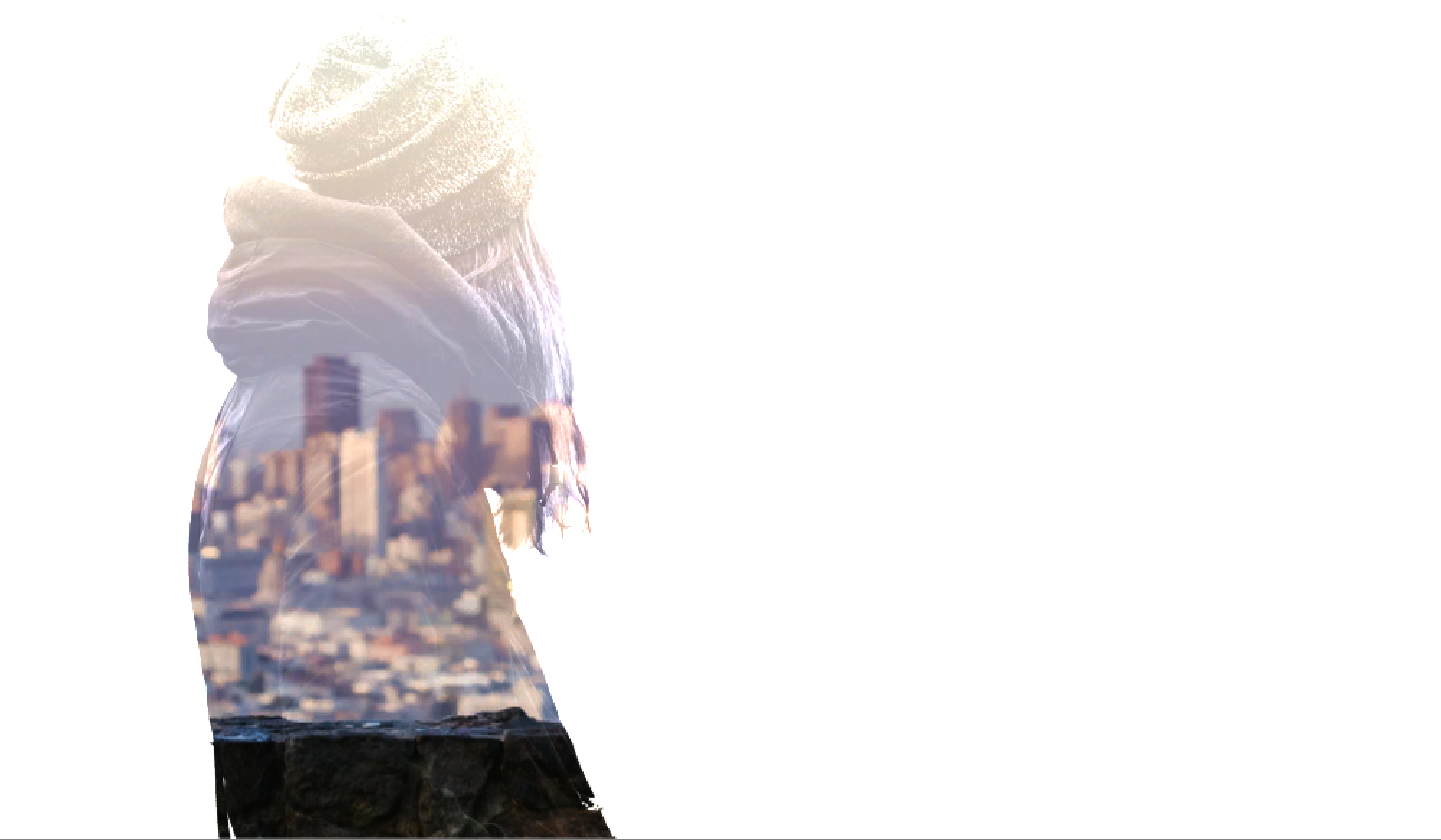
Let’s do a non-traditional blending using the concepts we just got! There’s a famous HBO serie I like called “True Detective”. The series’s opening is well known, and it uses this kind of effect:

Taking a look at the images we can say that there is an image in the background (some building environment)  and a second layer, our “character” who is masking the background. But, how is it masking? Well, making us closer let’s say  brighter  our mask or character is,the fewer background we can see , and darker our mask is, the more we can see of it.

Let’s Try!

Set an image into your unity project, it will be the background:


First, add to the scene as a sprite or a quad  with  mesh renderer and an unlit material with that picture as texture. Then, add the image who is going to be the mask:

Set the second image ( the one with just the girl)  as a texture of the material of the shader below:

Shader "Unlit/BlendShader_03"
{
	Properties
	{
		_MainTex ("Texture", 2D) = "white" {}
		_Color("Color", Color) = (1.0,1.0,1.0,1.0)
	}
	SubShader
	{
		Tags { "RenderType"="Transparent" }
		LOD 100

		Pass
		{
		Cull off

		 ZWrite off // don't write to depth buffer 
            // in order not to occlude other objects

         //Here is the blending directive!===>
         Blend  OneMinusSrcColor SrcColor  
			CGPROGRAM
			#pragma vertex vert
			#pragma fragment frag
			// make fog work
			#pragma multi_compile_fog

			
			#include "UnityCG.cginc"


			struct appdata
			{
				float4 vertex : POSITION;
				float2 uv : TEXCOORD0;
			};

			struct v2f
			{
				float2 uv : TEXCOORD0;
				UNITY_FOG_COORDS(1)
				float4 vertex : SV_POSITION;
			};

			sampler2D _MainTex;
			float4 _MainTex_ST;
			float4 _Color;

			v2f vert (appdata v)
			{
				v2f o;
				o.vertex = UnityObjectToClipPos(v.vertex);
				o.uv = TRANSFORM_TEX(v.uv, _MainTex);
				UNITY_TRANSFER_FOG(o,o.vertex);
				return o;
			}
			
			fixed4 frag (v2f i) : SV_Target
			{
				// sample the texture
				fixed4 col = tex2D(_MainTex, i.uv)  * _Color;
				// apply fog
				UNITY_APPLY_FOG(i.fogCoord, col);
				return col ;
			}
			ENDCG
		}
	}
}

What we are doing with this line:

         Blend  OneMinusSrcColor SrcColor  

It is,

Take the color from the background and subtract the color from the “mask”(the texture of our shader) and add the color of the mask to the buffer Color.

So if the “mask” texture is white, the contribution of the background will be zero, and the result will be white because of the color source of the mask.

On the other hand, if the value of the mask is for example grey, let’s say a a 0.5 contribution  from the background plus the source color to the buffer color.

It could sound a little confusing but just play around changing the textures and you will understand better the behaviour. I linked a video in case you just want to check out the result!


Analyzing and Emulating Limbo Style Shader

First of all, this article is an approach on how to make a game look like Limbo, the  game. I’m not saying that this is the way  Limbo creators did it.

Below we have an example of a photo and a video that show how the shader looks.

Analyzing the appearance

Firstly, we have to figure out what makes Limbo’style stand out. Knowing these attributes will let us translate it into requirements, and finally implement it in our shader.

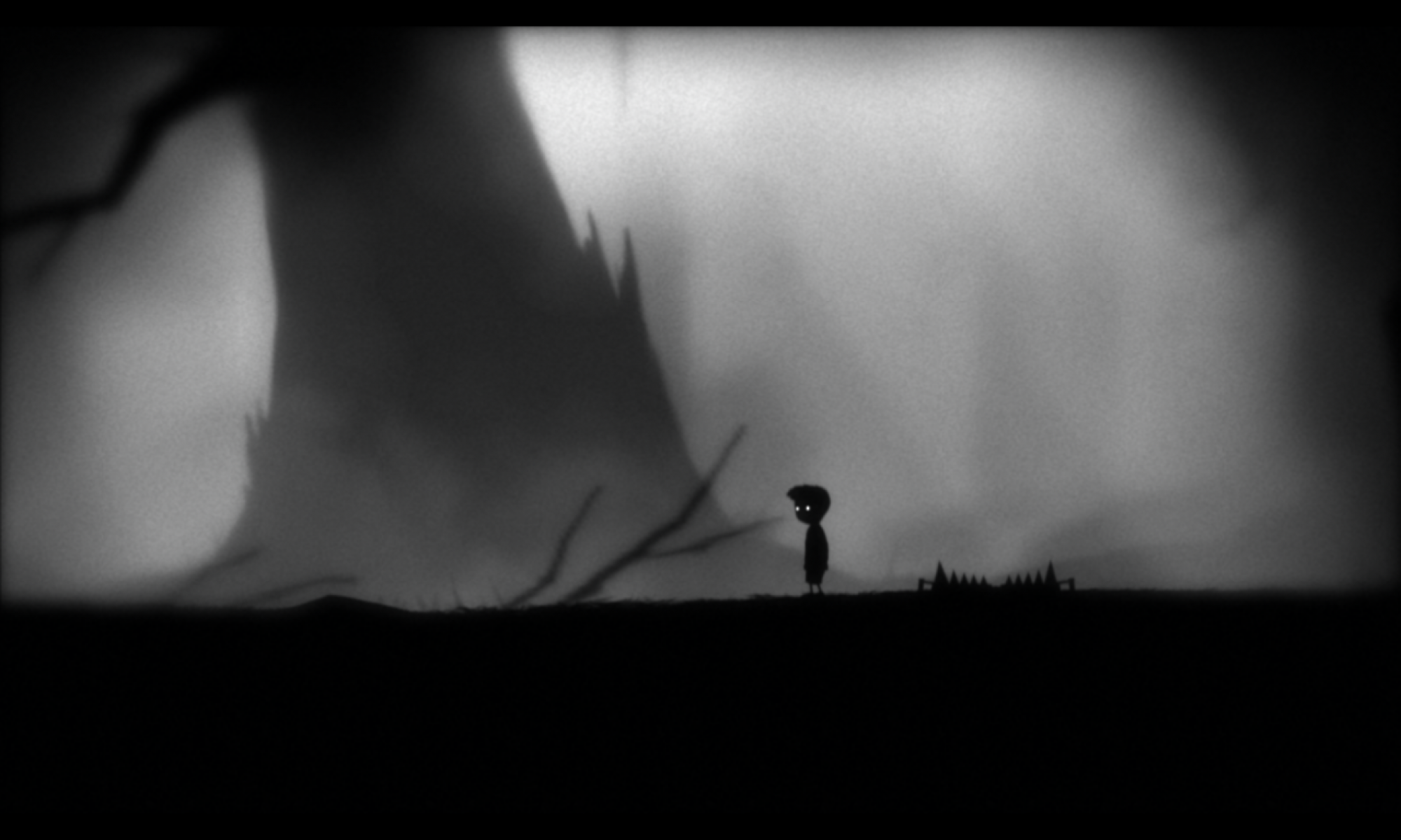
We can achieve the first step just looking at a screenshot of the game and describing it. Let’s practice, what attribute do you think makes the screenshot below special?

Tic tac! Time out! Well, I’m going to resume my answer into bullet points:

  • All the picture is in Black & White.
  • There’s some kind of vignetting.
  • Blur near to the borders of the picture.
  • Noise in the picture, like the noise generated by an old TV.


The work previously done is crucial and it will help us start building our shader.

To implement these requirements we’re going to use the game engine Unity 3D. In order to get your Unity scene ready to be able to implement an image processing effect, just go to this article.

You can find the complete shader at the bottom of this article. Anyway, I’m covering the fragment function (where is the limbo effect acting) step by step.

All the picture is in Black & White.


The first thing we do is turning our image into a gray value. That means, get the luminosity of the pixel.

fixed4 frag (v2f i) : SV_Target
{

   // sample the texture
   fixed4 col = tex2D(_MainTex, i.uv);
   //Apply the perception brightness proportion for each color chanel
   float luminosity = col.x * 0.3 + col.y * 0.59 + col.z *  0.11;
   return fixed4(luminosity,luminosity,luminosity,1.0);
			  
}

The fragment shader is receiving the UVs coordinates of the _MainTex and the  _MainTex, which is the rendered image. The UVs correspond to our screen coordinates being our left bottom screen the (0,0) and the upper right the (1,1).

We sample the texture and get the pixel we are currently processing by the GPU. Now, we extract the luminosity using the values:

Luminosity  =  channel red * 0.3f  + channel green * 0.58 + channel blue * 0.11;

Finally, our frag function returns a fixed4, initialising each value with the luminosity get before.

So right now every pixel of our image in turned into a luminosity value.

If we implement this fragment function, we’ll get a black and white effect.


Noise on the picture, like the noise generated by an old TV.


Now we have our first requirement done, let’s do the second one! This step consists of adding an old Tv noise appearance.

To achieve this effect, we just choose a cool noise image from the internet. For example:

So we add a new property to our shader in order to be able to set this texture in the material which will wrap the shader:

Properties
	{
		_MainTex ("Texture", 2D) = "white" {}
		_OldTVNoise("Texture", 2D) = "white" {}
		_NoiseAttenuation("NoiseAttenuation", Range(0.0,1.0)) = 0.5
		_GrainScale("GrainScale", Range(0.0,10.0)) = 0.5
		
	}

You can appreciate that the are more properties than the _OldTVNoise texture. They are going to be used as configuration values for the noise.

A look on how to proceed in the fragment function. What we are doing is just getting a color value from the noise texture, using the UVs coordinates from the rendered image and multiplying this value by our image grayscale luminosity value.

But, what we get here? I mean, yeah we are multiplying both textures but how it actually works? Well, If our rendered image has, for example, a value of 0.5, which is a gray value, and we multiply it by the value of the noise texture, for example, another 0.5, we’ll get a result of 0.25.  So we can appreciate that the rendered image will be affected by the noise texture, making it darker depending on the value of the noise texture.

fixed4 frag (v2f i) : SV_Target
{
      // sample the texture
       fixed4 col = tex2D(_MainTex, i.uv);
     //Apply the perception brightness proportion for each color chanel
      float luminosity = col.x * 0.3 + col.y * 0.59 + col.z *  0.11;
      //Sample the noise texture, multiplyng the UVs by _GrainScale to make it customizable
      //The _RandomValue is a float set externaly to make the noise move every frame in our screen
      fixed4 noise = clamp(tex2D(_OldTVNoise, i.uv*_GrainScale + float2(_RandomNumber,_RandomNumber)), 0.0, 1.0);
      //Multiplying both values
      return fixed4(luminosity,luminosity,luminosity,1.0)* noise;
}


Vignetting effect, LIKE a cinema projector.

Well, How can we achieve this? There is an easy way to do it: using the same technique used above.  Just multiply the result by another texture of a projector.

We declare in our properties block another variable for the vignette texture. And the fragment function should look like:

fixed4 frag (v2f i) : SV_Target
{
      // sample the texture
       fixed4 col = tex2D(_MainTex, i.uv);
     //Apply the perception brightness proportion for each color chanel
      float luminosity = col.x * 0.3 + col.y * 0.59 + col.z *  0.11;
      //Sample the noise texture, multiplyng the UVs by _GrainScale to make it customizable
      //The _RandomValue is a float set externaly to make the noise move every frame in our screen
      fixed4 noise = clamp(tex2D(_OldTVNoise, i.uv*_GrainScale + float2(_RandomNumber,_RandomNumber)), 0.0, 1.0);
      
      //===> Here we take the value of the vignette texture
     fixed4 vignetteFade = tex2D(_VignetteTexture, i.uv);
     
     //Multiplying  values
      return fixed4(luminosity,luminosity,luminosity,1.0)* noise*vignetteFade;
}

I’ve explained this way because is the easier and the cheapest for the GPU. In the shader shown in the video and image, the vignetting is generated by code and it is customizable.

I ain’t going to explain how to do it in this article because it will make it too large.  A clue how to do it, I’ve used the UV coordinates to know how far away the pixel is from the center of our image, and then, applying some kind of fade to black.

There are some more effects that I’ve used like the blur effect. I’ve written all the fragment function at the end of the article if you want to dig deeper.

In resume, to achieve a style just define your requirements and go through them step by step. Remember to work in an iterative way, the shader is something about perception, so how do you know your code is working properly if you don’t take a look time to time.

I hope you enjoy the article if you have some questions just comment or send me an email.

Here you can find the complete Pass including fragment function, it’s not all the shader, if you want to get it, please feel free to contact me.

		Pass
		{
			sampler2D _MainTex;
			sampler2D _OldTVNoise;
			float4 _MainTex_ST;
			float _ScreenPartitionWidth;
			float _NoiseAttenuation;
			float _GrainScale;
			float _RandomNumber;
			float _VignetteBlinkvelocity;
			float _VignetteDarkAmount;
			float _VigneteDistanceFormCenter;
			
			v2f vert (appdata v)
			{
				v2f o;
				o.vertex = UnityObjectToClipPos(v.vertex);
				o.uv = TRANSFORM_TEX(v.uv, _MainTex);
				return o;
			}
			float4 blur(sampler2D tex, float2 uv, float4 size)
			{
				float4 c = tex2D(tex, uv + float2(-size.x, size.y)) + tex2D(tex, uv + float2(0, size.y)) + tex2D(tex, uv + float2(size.x, size.y)) +
							tex2D(tex, uv + float2(-size.x, 0)) + tex2D(tex, uv + float2(0, 0)) + tex2D(tex, uv + float2(size.x, 0)) +
							tex2D(tex, uv + float2(-size.x, -size.y)) + tex2D(tex, uv + float2(0, -size.y)) + tex2D(tex, uv + float2(size.x, -size.y));
				return c / 9;
			}
			
			fixed4 frag (v2f i) : SV_Target
			{
				// sample the texture

				fixed4 col = tex2D(_MainTex, i.uv);

				//If the uv x cordenate is highter than _ScreenPartitionWidth we apply the b&w effect, if not, we apply the image render how it is.
			     if(i.uv.x >_ScreenPartitionWidth)
			     {
			      //This condition is done in order to draw a vertical line which is the frontier between the image processed and the normal image
			        if(abs(i.uv.x -_ScreenPartitionWidth) < 0.005)
			        return fixed4(0.0,0.0,0.0,1.0);

			        //Apply the perception brightness proportion for each color chanel
				float luminosity = col.x * 0.3 + col.y * 0.59 + col.z *  0.11;

				fixed4 noise = clamp(fixed4(_NoiseAttenuation,_NoiseAttenuation,_NoiseAttenuation,1.0) + tex2D(_OldTVNoise, i.uv*_GrainScale + float2(_RandomNumber,_RandomNumber)), 0.0, 1.0);
				float fadeInBlack = pow(clamp(_VigneteDistanceFormCenter -distance(i.uv, float2(0.5,0.5)) +  abs(cos( _RandomNumber/10 +  _Time*10*_VignetteBlinkvelocity))/4, 0.0, 1.0),_VignetteDarkAmount);
				float4 blurCol = blur(_MainTex, i.uv, float4(1.0,1.0,1.0,1.0));
				float blurValue = (blurCol.x * 0.3 + blurCol.y * 0.59 + blurCol.z *  0.11);
			     	return fixed4(luminosity,luminosity,luminosity,1.0)/blurValue * noise * fadeInBlack*fadeInBlack * blurValue;

			     }
			     else{
			      	return col;
			     }
			}
			ENDCG
		}
	}
}


Introduction to Processing image render effect in Unity

In this post, I’m going to cover an overview how unity works in processing camera effects or post-processing effects.

The point is once all your camera view has been rendered and it’s ready to be displayed on your screen, we take this “image-screen” and do some changes in order to make it look as we want (more contrast, brighter, blur effect, monochromatic effect…).

Unity will provide this image by the Monobehaviour’s event OnRenderImage. To make it works we have to follow just two  steps:

Step one

Create a script which implements the event and attach it to the camera of our scene.

using UnityEngine;

[ExecuteInEditMode]
public class ImageRenderedEffect : MonoBehaviour
{
    public Material processingImageMaterial;

    void OnRenderImage(RenderTexture imageFromRenderedImage, RenderTexture imageDisplayedOnScreen)
    {
        if (processingImageMaterial != null)
            Graphics.Blit(imageFromRenderedImage, imageDisplayedOnScreen, processingImageMaterial);
    }
}

OnRenderImage is called after all rendering is complete to render image.  You can read the documentation about this event here.  The public variable processingImageMaterial creates a field in our inspector where we can set the material we want to use in order to process the image.

The GraphicsBlit() function is some kind of magic function that let us set the rendered image to the material which will process it.  The first parameter is the rendered image, followed by the out RenderTexture, and the third is the material we want to use.

I know all the code above is a little tricky. But it’s something you have to do if you want to make postprocessing effect.


Step two

Create a shader and a material to wrap it. The shader will be the one who will process the rendered image. In this case, I’m going to create a simple “black and white” effect.

One key concept is that the _MainText property of the shader will be set by the function  GraphicsBlit() . It’s important to know this issue because we work with the _MainText  which is the one who contains the rendered image. The UVs will be set too with the UV of our screen. So we are going to work as the Rendered Image is a textured set in a mesh plane which fits all our screen (from corner to corner).

Shader "Unlit/B&WEffect"
{
	Properties
	{
		_MainTex ("Texture", 2D) = "white" {}
		_ScreenPartitionWidth("ScreenPartitionWidth",  Range (0.0, 1.0)) = 0.5
	}
	SubShader
	{
		Tags { "RenderType"="Opaque" }
		LOD 100

		Pass
		{
			CGPROGRAM
			#pragma vertex vert
			#pragma fragment frag
		
			
			#include "UnityCG.cginc"

			struct appdata
			{
				float4 vertex : POSITION;
				float2 uv : TEXCOORD0;
			};

			struct v2f
			{
				float2 uv : TEXCOORD0;
				UNITY_FOG_COORDS(1)
				float4 vertex : SV_POSITION;
			};

			sampler2D _MainTex;
			float4 _MainTex_ST;
			float _ScreenPartitionWidth;
			
			v2f vert (appdata v)
			{
				v2f o;
				o.vertex = UnityObjectToClipPos(v.vertex);
				o.uv = TRANSFORM_TEX(v.uv, _MainTex);
				return o;
			}
			
			fixed4 frag (v2f i) : SV_Target
			{
				// sample the texture

				fixed4 col = tex2D(_MainTex, i.uv);

				//Apply the perception brightness proportion for each color chanel
				float brightness = col.x * 0.3 + col.y * 0.59 + col.z *  0.11;

			     //If the uv x coordinate is higher than _ScreenPartitionWidth we apply the b&w effect, if not, we apply the image render how it is.
			     if(i.uv.x >_ScreenPartitionWidth)
			     {
			      //This condition is done in order to draw a vertical line which is the frontier between the image processed and the normal image
			        if(abs(i.uv.x -_ScreenPartitionWidth) < 0.005)
			        return fixed4(0.0,0.0,0.0,1.0);

			     	return fixed4(brightness,brightness,brightness,1.0) ;
			     }
			     else{
			      	return col;
			     }
			}
			ENDCG
		}
	}
}

Here you can see a video applying the effect  to a scene with a couple of 3D low-poly flowers downloaded from asset store created by Chlyang,

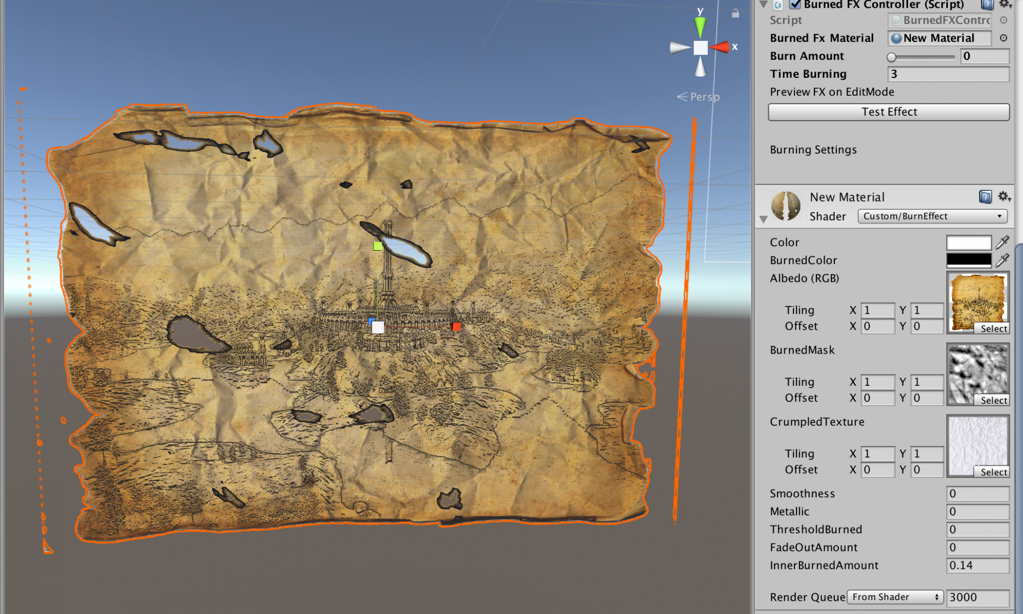
Burning Paper FX Shader.

This is the shader I’m working right now.


At the very beginning, it was created to be a dissolve shader effect. I decided to pivot to a burning paper effect. The reason: I was reinventing the wheel.  The asset store ( the unity’store where you can buy all your resources for video games) was full of dissolve shaders, a lot of people like me thoughts it was a great idea too.


But I’ve realized all the shaders were very generic shader. Obviously, they are dissolve shaders, but What was dissolving?  The answer is everything and nothing.  So I started to work on the idea of doing a dissolve shader for only one material… the one who is often dissolved in games, paper. So I’ve been working on this shader on my free time, trying to figure out how the paper behaves, how It looks… As far I’ve got this, but I have more effect to implement in the shader. I hope to show you in next posts.

.